Introduction to Software - Part 2
![]() Click HERE to download a printable copy of Chapter 2
Click HERE to download a printable copy of Chapter 2
Introduction to Software - Part 1
Introduction to Software - Part 2 <- You are HERE
USER'S MANUAL V3.2: CHAPTER 2
Introduction to Software
STRUCTURED PROGRAMMING
Similarly to keeping your wiring neat and well documented, there is a lot to be said for doing the same with your software. Well documented programs, with plenty of meaningful remarks spread throughout the code, are well worth the extra effort.
Whole books are written on structured programming which from our view might reflect on how best to set up a program's organization. Typically however, for real-time applications, the best – from both a processing time as well ease in understanding perspective – is straight line code. Thus even with modular programming (covered in Chapter 13), it is still best to employ straight line programming within each module.
In my opinion, many professional programmers and some C/MRI programmers, complicate their approach in the pursuit of optimized Structured Programming. In doing so, they tend to include a large variety of different branching-type statements such as DO WHILE, DO UNTIL, EXIT DO, IF-THEN-ELSEIF-THEN-ELSEIF-THEN-ELSE-END-IF, ON…GOSUB, ON…GOTO, CHAIN, WHILE…WEND, FOR EACH…NEXT and a whole bunch more. I recommend taking the exact opposite approach preparing C/MRI programs. The guidelines I like to follow are:
- Use a very small subset of basic instructions and then use these same statements over-and-over again with very minimal changes like substituting different numbers and variable names.
- Use only the IF-THEN and the IF-THEN-ELSE statements for conditional branching.
- Use only the GOTO statement for unconditional branching and then only for making short forward jumps to branch around short sections of code.
- Use abbreviated yet still meaningful variable names and statement labels.
- Include one or more documentation lines at the beginning of every short block of statements to describe the codes purpose and action being taken. In addition, for added clarity, append further documentation to subsequent statements.
- Use a single global area to define all variables that must be accessible by two or more modules. This item applies only when using CALL statements (covered in Chapter 13 and further used in Chapters 14 and 15) which are encouraged for use within most medium to large application programs.
In summary you might say that, “I limit myself to using a minimum subset of statements that gets the job done.” Likewise, I purposely stay away from using alternate statements that might appear as being more elegant or a “better way to execute code.” My recommended procedures may not take advantage of the most powerful aspects of a given language or reduce the number of coding lines but they do provide programs that are easy to generate, to understand and that work exceptionally well. This approach is valid independent of whether we are programming in QuickBASIC or Visual Basic. My motto in all C/MRI programming is, “Keep your programming simple, straightforward and easy to understand!”
It is my belief that the vast majority of C/MRI interested readers have never been exposed to programming. By demonstrating that a user need only learn a very small set of statements and then to use these repeatedly, with minimal changes, is the best approach to helping more railroaders take advantage of everything a computer can offer to increase hobby enjoyment. My underlying goal is to make every program come as close as I can to read like reading the English language.
I spent a majority of my 35 year engineering career creating and supervising the creation of real-time software systems for the aerospace industry. Keeping programming simple, straightforward and easy to understand while at the same time doing the job that needs to be done is a worthy and achievable goal.
|
****Important Point**** New C/MRI users simply need to learn a few basic programming statements. Using these statements repeatedly – with very minimal changes – new users (or any user) can generate almost any desired C/MRI application program. |
The above is true if all you want to do is monitor train location and light a few signals, control grade crossing protection devices, or if you want to prototypically signal a vast network of trackage using multiple head signaling. It applies equally well to the implementation of Computer Cab Control with interfacing to a lever-type CTC machine and an Entrance-Exit type interlocking plant.
To me, being able to accomplish all the above while at the same time keeping the program simple, straightforward and easy to understand is what C/MRI programming is all about!
ESTABLISHING PROGRAM FLOW
With all variables named, and their memory location automatically defined by QuickBASIC or by Visual Basic, (or by whatever language you are using), the C/MRI application program merely executes the program statements one statement at a time. Unless directed otherwise the application program executes the statements in a linear fashion starting from the top and sequentially working through to the bottom of the program. For example, Fig. 2-12 includes a grouping of typical programming type statements.
|
REM**SAMPLE CODE LINES FROM INITIALIZATION SECTION DRK = 0 GRN = 1 YEL = 3 RED = 2 REDRED = 10 REDYELRED = 46 REM**SAMPLE CODE FROM REAL-TIME LOOP SECTION TS52LAB = REDRED TS52RA = GRN TS52RC = RED TS72RA = RED TS72RB = RED TS72LABC = REDYELRED |
Fig. 2-12. Sequentially stepping through typical programming statements
Proceeding sequentially through the initialization statements, the PC program takes the value 0 and places it into the memory location named DRK. Likewise it places the value 1 in the memory location named GRN, 3 in the location named YEL, 2 in location named RED, 10 in location named REDRED and 46 in location named REDYELRED. Later on, I will show how we arrive at these numbers. In this case they happen to be the standard signal aspect constants for searchlight signals. Because the values do not change throughout the program’s operation, it is important to note that variables can hold constants just as well as variable numbers. For this reason I will frequently refer to non-changing variables such as DRK, GRN and RED as constants, in this case signal aspect constants, rather than variables.
While executing the statement examples within the real-time loop, the first statement sets Trackside Signal 52LAB to red over red. It does this by copying the value stored in memory location named REDRED, which is decimal 10, into the memory location for TS52LAB. It should be noted that executing this statement changes only the signal’s value as stored in the computer’s memory and does not change the actual trackside setting. The latter only occurs when the signal values are transmitted or written to the railroad.
Taking the statements in sequential order, as the PC executes the program, the next statement sets TS52RA to green, followed by setting TS52RC to red, etc., through to setting the 3-headed Trackside Signal TS72LABC to red over yellow over red.
Without specific statements to alter the program flow, the PC simply executes the statements in sequence from top to bottom. Although it makes no difference how program statements are executed, multiple statements can be placed on the same line. For example the bottom four statements in Fig. 2-12 could be written as follows and will provide the exact same results.
TS52RC = RED: TS72RA = RED: TS72RB = RED: TS72LABC = REDYELRED
The colon is use to separate multiple statements on a given line.
IF-THEN Conditional Branching
Using the simple power of IF-THEN logic, what can be accomplished by a new C/MRI user is truly amazing. The application of this statement is so easy to understand. We live with the logic of it throughout every day of our lives:
- IF Janet comes home before noon THEN I am taking her to the movies
- IF Billy comes over to visit THEN we are going to run some trains
- IF there is a “special” on apples today THEN I am going to buy a peck
Application of the IF-THEN-ELSE statement is almost as easy to understand.
- IF Billy comes over THEN we will run trains ELSE I will clean the garage
(As a side note, I sure hope Billy comes over)
- IF it rains today THEN I will get ready for that op session ELSE I will mow the yard
Applying the same logic to programming our model railroads we have:
- IF Track Alignment Button 7 is pressed THEN Switch Motor 5 is set normal and 9 is set reversed
- IF Signal 24 is red THEN Signal 32 is yellow ELSE Signal 32 is green
All a new C/MRI user needs to do is to combine the logic power of the IF-THEN statement with a few other statements like FOR-NEXT, GOTO and GOSUB and creation of some very effective C/MRI application programs is now possible!
The IF-THEN statement is a natural step for altering program flow based upon different situations. For example let’s assume we need to set SE(3) = GRN if the switch motor for Turnout 9, denoted as say SM(9), is normal, or alternatively to set SE(3) = RED if SM(9) is reversed. The way we will most frequently alter program flow is using the IF-THEN statement. One way to handle this situation is to write:
SE(3) = RED
IF SM(9) = TUN THEN SE(3) = GRN
Firstly, Signal SE(3) is initialized to red, followed by executing the next statement, which is the IF-THEN statement. Here IF SM(9) = TUN, i.e. if the turnout is in its normal position, the IF statement is true so the program alters its flow to execute the statement immediately to the right of THEN. This sets SE(3) to green followed by executing the next statements below the IF, represented by the three dots. IF SM(9) is not equal to TUN, i.e. the turnout is reversed, the IF statement is false and the program does not execute the statement to the right of THEN and proceeds directly to the statements represented by the three dots.
As an alternative we could use the IF-THEN-ELSE statement to achieve the same results:
IF SM(9) = TUN THEN SE(3) = GRN ELSE SE(3) = RED
In this case, if SM(9) = TUN, i.e. the turnout is normal, then the statement SE(3) = GRN is executed prior to moving on to the statements represented by the 3 dots. Else if SM(9) is not normal, i.e. it is reversed, the statement SE(3) = RED is executed before continuing with the statements represented by the 3 dots. Here we have altered the program flow through two different paths dependent upon the state of the switch motor and its corresponding turnout position.
It is quite easy to run out of line space when using IF-THEN and IF-THEN-ELSE statements. For these situations the Block IF format comes to the rescue, for example as with the following typical block of software diode matrix statements:
IF TB(16) = TBP THEN
SM(1) = TUN: SM(2) = TUR: SM(3) = TUN: SM(4) = TUN: SM(5) = TUR
SM(6) = TUR: SM(9) = TUN: SM(11) = TUR: SM(14) = TUN
END IF
If Turnout Pushbutton 16, named with variable TB(16), is pressed, denoted by variable TBP for Turnout Button Pressed, then the block of statements between the IF-THEN and the END IF statements is executed. However, if TB(16) is not pressed the block within the IF statements is skipped.
The Block IF-THEN-ELSE works much the same way, as for example:
IF {expression} THEN
{‘A’ block of statements}
ELSE
{‘B’ block of statements}
END IF
IF the expression between the IF and the THEN is true, then only the A block of statements is executed. However, if the expression is false only the B block of statements is executed. Once either the A block or the B block of statements is executed the program continues with the statements represented by the 2 dots.
It is important to note how selected statements are indented in the above examples. Following this procedure makes reading easier and is a recommended programming practice. For example, indenting all the statements between the IF-THEN statement and the corresponding END-IF statement clearly indicates which statements are included within the use of the Block IF format.
FOR-NEXT Loops
The FOR-NEXT loop, introduced previously, also alters program flow. For example:
FOR IJ = 1 to 100
Signal(IJ) = RED
NEXT IJ
Here the program keeps looping through these 3 statements starting with IJ = 1, and with each iteration of the loop the value of IJ is incremented by 1. Once the NEXT IJ statement is reached with IJ = 100 there is no more incrementing to perform. Thus,the program flow continues by executing whatever statements exist below the NEXT IJ statement as represented by the 3 dots. The above statements could also be written on one line as:
FOR IJ = 1 to 100: Signal(IJ) = RED: NEXT IJ
There are many other types of conditional logical branching, such as the ELSE-IF, the DO UNTIL, and the DO WHILE statements to name a few. However, making use of a bunch of additional statements really is not necessary to our C/MRI programming. Therefore, in support of my philosophy to keep programming simple, straightforward and easy to understand, the examples in this manual do not use these additional statements.
|
****Important Point**** All you need to learn is a few basic statements and to use these statements repeatedly – with minimal changes – you can generate any desired C/MRI application program |
GOTO Statements
The GOTO statement creates what is called an unconditional branch. It is the most direct method of altering program flow. Each use of GOTO requires a “branch-to” label immediately to the right of the GOTO command. A frequent example we will be using is GOTO BRTL. Each time the program execution reaches the statement GOTO BRTL, the program diverts from its sequential execution of statements and immediately branches to execute whatever statement is located after the BRTL label. For example, consider the following programming situation:
BRTL: {label for next statement executed after GOTO BRTL statement is executed]
GOTO BRTL
The addition of the colon after the BRTL label is required to indicate to the basic compiler that the characters preceding the colon form a label. It should be noted that the label can be placed anywhere within the program. When the program execution reaches the GOTO BRTL statement, an unconditional branch is executed to the label BRTL regardless of where the BRTL is located. The above coding illustrates what I call a “backward branch”. This is where a branch is created back into the program, at a point before the GOTO instruction.
Care should be taken to avoid backward branching. Why? When executing backward branching several times within a program it is extremely easy to lose track of how the program flows. Also, with backward branching it is easy to put your program into an infinite loop, where you branch back, move forward, branch back, move forward and branch back ad infinitum – resulting in a program “lock up” and gets you nowhere. As dictated by good programming practice, the only place I will be using backward GOTO branching in our C/MRI application programs is at the end of our real-time loop. That is where we need to return to the beginning of our real-time loop, i.e. GOTO BRTL, in order to keep our program looping.
By contrast, short forward GOTO branching is extremely useful in C/MRI programming. Most signal programming involves initializing signals to RED and then checking a number of conditions to see if signals can change to a more favorable aspect. Anytime a condition is found whereby a signal needs to be retained at RED, you simply branch directly to the starting point for determining the next signal – keeping the previous signal at RED. Such programming becomes second nature once we complete a few signaling examples in Chapter 8.
The major ground rule to effectively use forward GOTO branching is to keep multiple branches short and where possible to the same forward point. This is the procedure I will follow in all our application program examples.
GOSUB Statements
The GOSUB statement performs much like the GOTO statement with one major difference. The GOSUB label statement causes a branch to the label but in doing so the software saves the location of the program at the statement immediately following the GOSUB statement. This way, once the program continues with executing the statements following the label and it comes to a RETURN statement, the program returns (using the saved location) to execute the statement immediately below the GOSUB.
Basically, incorporating a GOSUB statement enables the program to branch to another block of statements, called a subroutine, and then to RETURN to the statement immediately following the GOSUB. Fig. 2-13 illustrates the situation.

Fig. 2-13. How a GOSUB functions
Note that the branch-to label contained within the GOSUB statement coincides with the label used to start the subroutine. In this case, I have used the name INIT to correspond to the name given to the subroutine within the GOSUB version of our standard Serial Protocol Subroutine package (SPSBG). Subroutine INIT is invoked each time we want to initialize a serial node.
Using GOSUB comes in handy when you want to branch to do something special, especially if you want to do this repeatedly or from several different locations within a program. Each time the GOSUB is executed you always return back to continue where you were before branching. When we begin serial programming examples, I will frequently use the GOSUB statement each time we initialize a node, or write outputs to a node or read inputs from a node.
The subroutine code using GOSUB, although it may appear to be separate from the main program, actually remains a part of the mainline program. This means that all variables are equally available to the main program code and to the subroutine code. Therefore, for example, if you happen to set SE(45) = REDRED prior to the GOSUB execution and you added a PRINT SE(45) statement in the subroutine code, it would print out the red over red status of Signal East 45. Likewise any variables defined in the subroutine are available in the main body of the program.
For entry level programming and for programming small to medium systems, the availability of all variables across subroutine boundaries can be of significant advantage. You only have one overall set of variables and they are all available no matter what particular area of the program is being written.
As your programming becomes more advanced and/or you tackle larger system applications, it is often desirable to use CALL statements rather than GOSUB statements. When using a CALL statement the subroutine being called actually becomes a separate program module. I will cover modular programming and the use of the CALL statement in Chapter 13 and then use the techniques in Chapters 14 and 16.
SERIAL PROTOCOL SUBROUTINES
Serial interfacing requires the ability to convert the data format from parallel to serial and vice versa, coupled with the ability to send card addresses and data in serial form over the same wire. Special hardware built into PCs and into the Microcontroller chips used with the SMINI, SUSIC and USIC automatically performs the required parallel-serial conversions. We will make use of special software, typically referred to as Serial Protocol Subroutines, to interact with the hardware.
The protocol subroutines we will use with the C/MRI automatically form the required packets of information, called messages, to be transmitted to the external hardware. It handles the messages received from the interface hardware. The software inserts special control characters to mark the beginning and end of transmissions, as well as define which bytes are addresses and which are pure data. This may sound complicated, but I have done the hard work for you by providing standardized routines to carry out the C/MRI protocol. All you need to do is to initialize a few variables and then just invoke the appropriate protocol subroutine.
To meet different programming desires, I provided three new and different serial protocol packages with the release of the Version 3.0 C/MRI User’s Manual. Table 2-1 summarizes these packages including the package name along with a brief description and example applications.
Table 2-1. Standard Serial Protocol Subroutine (SPS) packages
|
Name |
Description |
Example Application Areas |
|
SPSQBG |
Serial Protocol Subroutine Package using QuickBASIC’s GOSUB Option |
Typically used for smaller applications programmed in such languages as Basica, GW Basic, QBasic, QuickBASIC and Power Basic operating under DOS |
|
SPSQBC |
Serial Protocol Subprogram Package using QuickBASIC’s CALL Option |
Typically used for larger applications programmed in QBasic and QuickBASIC operating under DOS and Power Basic operating under DOS or Windows |
|
SPSVBM |
Serial Protocol Subprogram Package using Visual Basic’s CALL Option with Microsoft provided MSComm |
Typically used for Visual Basic applications operating under Windows using Microsoft provided MSComm for serial communications |
Although not specifically provided at this time, it is reasonable to expect that an equivalent standard Serial Protocol Subroutine package will become available to support of the C-based family of languages.
Using one of the standard Serial Protocol Subroutine packages offers a big advantage in that all the serial data communications between the PC and the C/MRI hardware is handled for you automatically. You do not need to be concerned about any of the details. At a point in your program where you want to initialize a node you add the statement GOSUB INIT, or CALL INIT. At the point where you want to transmit outputs to a C/MRI node you add the statement GOSUB OUTPUTS or CALL OUTPUTS. Finally, when you want to receive inputs back from a node you include a GOSUB INPUTS or a CALL INPUTS. Table 2-2 summarizes the situation.
Table 2-2. Application of INIT, OUTPUTS and INPUTS to make serial I/O easy
|
Statements used with GOSUB option |
Statements used with CALL option |
Function performed |
|
GOSUB INIT |
CALL INIT |
Initializes a node (USIC, SUSIC or SMINI) |
|
GOSUB OUTPUTS |
CALL OUTPUTS |
Transmits all output bytes to a node |
|
GOSUB INPUTS |
CALL INPUTS |
Receives all input bytes from a node |
Understanding the internal details of the different Serial Protocol Subroutines is not important to their successful application. However, for readers interested in the details concerning these packages and how they operate, such material is covered in Appendix B for the QuickBASIC version and in Appendix C for the VB version. Also, the source code for each package is provided on the disk enclosed with this manual. Making effective use of INIT, OUTPUTS and INPUTS subroutines becomes second nature once we get into Basic Programming Examples in Chapter 7 and into the numerous application examples covered in Chapters 9, 12, 13, 14 and 16.
|
****Important Point**** Reader’s desiring to update existing C/MRI programs, so that they make use of the updated Serial Protocol Subroutines presented in this manual, should consult the last sections of Appendix B for a list of the steps required to make the conversion. |
BINARY NUMBER SYSTEM
When we talk to a computer, we use the decimal number system for the most part: the digits 0, 1, 2, 3, 4, 5, 6, 7, 8, and 9. The computer, however, uses a binary number system which consists of only two digits, 0 and 1, to do everything we do with 0 through 9.
Computers use the binary system, because it is very easy to handle this system electronically. Inside a computer are millions of electronic switches, transistors that store and control the flow of electrical signals. For example, a midrange Pentium chip has over three million transistors and that is only a small fraction of the total in a Pentium-based system. You can think of these transistors as if they were switches, like those in Fig. 2-14.
Each switch is separately controlled and can be either on or off, representing a single binary digit. When the transistor is on, then the value is 1 and the value is 0 when the transistor is off. A single switch can represent only two codes, but a pair can represent four, equivalent to decimal numbers 0 through 3. Each time a switch is added, the number of codes that can be represented doubles. Three switches can represent eight binary codes, four switches can represent 16, five switches can represent 32, six switches can represent 64, and so on.
The abbreviation for a single binary digit is bit. A bit can have only two states, but they may be referred to as on or off, high or low, true or false, +5V or 0V, as well as 1 or 0. The personal computers you will want to devote to C/MRI applications are either eight-, sixteen- thirty two- or sixty four-bit machines, which means that their electronic switches are arranged in groups of 8, 16, 32 or 64. A group of eight contiguous bits is called a byte, and as Fig. 2-14 shows, it takes eight binary switches to represent, or store, one byte of information.
If all eight switches are on, they indicate binary 11111111, which is equivalent to decimal 255. The decimal equivalent is the sum of the decimal equivalent values of each switch position that is turned on. The value is read from right to left and each switch doubles in decimal equivalent value. Each switch that is off equals zero, therefore, one byte can represent all decimal numbers between 0 and 255, a total of 256 binary codes.

Fig. 2-14. Binary codes
Table 2-3 shows the relationship between the number of address bits and the size of memory that a computer can address. The entries are simply powers of two. For example, a 16-bit bus supports an address space of 216 or 65,536 decimal locations that can be individually addressed.
In computer jargon, 65,536 is referred to as 64K bytes, or 64KB for short. In the general sciences, the symbol K typically stands for Kilo, Greek for 1000, however, in the computer industry K stands for 210 or 1024. This difference can be confusing, but in this manual K, or Kilo, will always be 1024.

Table 2-3. Address bits and memory size (powers-of-two)
When dealing with computers, the 1024 interpretation is handiest since computers “think” in powers of two, i.e. the binary number system. Likewise, in the computer field, M (standing for Mega or million), is equated with 220 or 1,048,576 locations and G (standing for Giga meaning giant in Greek or billion), is equated to 230 or 1,073,741,824. Note that M = K times K and G = K times K times K or more simply M times K. It is also interesting that each time you add a single bit you double the address space.
In Table 2-3 numbers, for instance 1, 2, 4, 8, 16, 32, 64, 128, 256, 512, and 1024, coincide with numbers we will be using throughout this manual. Virtually every number we use with computers has its roots in this powers-of-two table. We’ll use these relationships extensively as we proceed through this manual so you might find it handy to refer back to Table 2-3 when needed.
Binary is good for computers, but cumbersome for humans, so I will not deal in binary any more than absolutely necessary. One reason binary is cumbersome is that it takes a combination of eight 1's and 0's to represent a byte. A decimal number from 0 to 255 can also define the contents of a byte, but it is difficult to see the correspondence between the decimal number and the binary bit pattern. This is where the hexadecimal number system comes to the rescue.
HEXADECIMAL NUMBER SYSTEM
I have pretty well eliminated the use of hexadecimal numbers in this version of the C/MRI User’s Manual and in the Railroader’s C/MRI Applications Handbook. Therefore you may want to skip this section and come back to it later if a need arises. However, for those interested, I will go ahead and explain hexadecimal in case you run across its usage as part of the numerous discussions and application examples found on the C/MRI User’s Group at http://groups.yahoo.com/group/cmri_users.
The hexadecimal number system has 16 digits, or characters: 0 through 9 plus A through F. The letters are symbols used as digits, with A = 10, B = 11, C = 12, D = 13, E = 14, and F = 15. These 16 digits, 0 through F, can represent all possible bit combinations for a 4-bit group, sometimes called a nibble. A nibble represents half a byte. Fig. 2-15 shows corresponding hexadecimal, decimal, and 8-bit binary-coded numbers. A complete table would take 256 rows, 0 through 255, so I have eliminated many higher order rows.

Fig. 2-15. Hexadecimal, decimal and binary numbers
Being able to eliminate these rows, yet still have all the information we need, is one reason hexadecimal is so handy. It takes only two hexadecimal characters to represent any eight-bit binary code, a byte. That is convenient, but the main advantage of hexadecimal is the ease of converting binary to hex and hex to binary – much easier than with decimal numbers.
You can ignore all entries in Fig. 2-15 except those shown in bold type face. These are the hexadecimal numbers 0 through 9 followed by A through F, the corresponding decimal numbers 0 through 15, and the rightmost four zeros and ones in the binary column corresponding to decimal numbers 0 through 15.
This small portion, highlighted with a heavy outline border, is the only part we need to understand, because everything else can be derived from it. For example, a hexadecimal 11 is binary 0001|0001, a hex BB is 1011|1011, and a hex 1B is 0001|1011. The left hex character defines the left four binary bits, and the right hex character defines the right four bits. This can be very useful when you write application software to use with your C/MRI. For example, users employing languages such as Pascal and C typically make extensive use of hexadecimal. Whenever I use hexadecimal numbers, I either append a lower case h, so hex number D9 will appear as D9h or I write the number in the format 0xD9.
COUNTING CARDS/NODES USING NUMBER ZERO
Writing the original Model Railroader C/MRI series I debated whether to illustrate counting nodes, and I/O cards, starting with the numeral 0 or the numeral 1. In the computer world there are advantages to start counting with 0. However, almost since the beginning of time people have always counted 1, 2, 3,…. versus starting counts as 0, 1, 2, 3,… Therefore, figuring it would be easier to understand, I elected to stick with 1, 2, 3,… when counting nodes and I/O cards.
Over time though, I have found that counting cards as 1, 2, 3,… has created confusion when setting C/MRI card address DIP switches that require counting cards as 0, 1, 2, 3... The result was that the user always needed to subtract 1 from the card number when setting the card’s DIP switch. This got to be such a nuisance that starting with Version 3.0 of the C/MRI User’s Manual, the counting sequence for nodes and cards is changed to 0, 1, 2, 3,… that is the first node in a distributed serial system is now called Node 0 and the first I/O card within any given node is now called Card 0. This makes it easy because the node and card numbers are in exact agreement with their respective DIP switch settings.
Although certainly not essential to correctly count cards and set DIP switches, it can be interesting to look a little further into counting procedures. The decimal number system is based upon using 10 numerals or digits. Although many people may think of the 10 numerals as being the numbers 1 through 10, in actually, they are the digits 0 through 9. Every decimal number is constructed from these 10 digits 0 through 9. Thus, you could count on your fingers saying 0, 1, 2, 3,… that is your 10 fingers are numbered 0 through 9. When you increment 1 above the maximum digit count of 9, you get a 10 (a one-zero), which in reality is a carry of 1 with the base digit starting again at 0.
The same is true for the binary number system. Every binary number is constructed from its 2 numerals 0 and 1. When you increment 1 above the maximum base count of 1 you get 10 (one-zero), which in reality, is a carry of 1 with the base digit starting again at 0.
With the above in mind, take a look back at Fig. 2-15 to see how counting accumulates in binary, decimal and hexadecimal. In decimal, each time we increment a 9 we carry over 1 to add the next column and return the base column to 0. We do the same in binary, where each time we increment 1 we carry over 1 to add the next column and return the base column to 0. As a reinforcing experience, and without using Fig. 2-15 as a crutch, start at 0000 and try counting in binary. Take a piece of scrap paper and write down your counts in a vertical column as:
0000
0001
0010
Generating the rest of the sequence is up to you. Just remember, for each column, anytime you add 1 to 1 you get 0 with a carry over of 1 to the next column. When you are done, check your results to make sure they agree with the rightmost column in Fig. 2-15.
If you get as far as 1111, which corresponds to the decimal number 15, you should have counted 16 different entries numbered 0 through 15. These entries could be, for example, 16 I/O cards numbered 0 through 15. Or they could be 16 C/MRI system nodes numbered 0 through 15.
In Fig. 2-15, the decimal column denotes the card, or node, number while the binary column is used to set the corresponding card address DIP switch segments, where 0 equates to a switch segment turned off and 1 equates to switch segment turned on. Thus, Card 0 corresponds to having all switch segments off. Card 1 then corresponds to having the rightmost segment turned on. Card 2 corresponds to having the second from the right switch segment on, and so forth.
Using this starting from zero card/node numbering procedure, it is always best to ignore DIP switch setting tables found in earlier C/MRI and UCIS publications and stick with the updated numbering system introduced with V3.0 of the C/MRI User’s Manual and V3.0 of the Railroader’s C/MRI Applications Handbook. That way, everything is consistent between card number and DIP switch setting.
If you ever need to convert from binary to decimal, it is quite straightforward following the procedure illustrated in Fig. 2-14. Each binary bit position has a weighted decimal value equal to, from right to left, 1, 2, 4, 8, 16, 32, 64 and 128.
For readers inclined toward a deeper mathematical understanding, the weighted decimal value of each bit position is simply the number 2 raised to the power denoted by the bit position. For example, bit position 0 has the weighted decimal value of 20 or 1. Bit position 1 has the weighted decimal value of 21 or 2 while bit position 2 has the weighted decimal value of 22 or 4, bit position 3 has the weighted decimal value of 23 or 8, and so forth up to bit position 7, which has the weighted decimal value of 27 or 128.
Table 2-4 summarizes the weighted decimal value of each bit position within an 8 bit byte. To obtain the decimal equivalent for any 8-bit byte, simply add up the weighted decimal values for each bit that is turned on.
Table 2-4. Equivalent decimal value of each bit position within an 8-bit byte
|
Bit Position |
7 |
6 |
5 |
4 |
3 |
2 |
1 |
0 |
|
Decimal Value |
128 |
64 |
32 |
16 |
8 |
4 |
2 |
1 |
For example, with all 8 bits turned on, a binary 11111111, the decimal value of the byte is calculated as 128 + 64 + 32 + 16 + 8 + 4 + 2 + 1 which equals 255. With all 8 bits turned off, binary 00000000 is calculated as the sum of all zeros for a decimal value of 0. This confirms what we said earlier that an 8-bit byte can store 256 different values 0 through 255.
Selecting an in between binary number of say 01001011 corresponds to a decimal equivalent value of 0 + 64 + 0 + 0 + 8 + 0 + 2 + 1 which adds up to be 75. If you are interested in perfecting your skills in this area, pick a few of the binary entries in Fig. 2-15 and compute the corresponding decimal equivalent. Check your results against those shown in Fig. 2-15 to make sure you are doing the math correctly.
When DIP switch settings are necessary, I’ll present tables that illustrate actual switch setting for different card numbers. Therefore, doing the math is seldom required. However, once you have the above math understood, with a little practice, you will easily be able to read DIP switch settings as decimal numbers as well as binary.
NODE AND I/O CARD ADDRESS DIP SWITCH SETTINGS
Fig. 2-16, contained on the following page, pictorially shows DIP switch settings for different card and node numbers (addresses). Using this circumvents the need to do the mathematics for most addresses. Keep it handy to use over and over again each time there is a need to set a card or node address DIP switch.
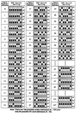
Fig. 2-16. DIP switch settings for different card/node numbers (addresses)