DCCOD TRACK OCCUPANCY DETECTOR
![]() Click HERE to download a printable copy of Chapter 4.
Click HERE to download a printable copy of Chapter 4.
Handbook v3.0: Chapter 4
DCCOD TRACK OCCUPANCY DETECTOR
If your railroad uses DCC for train control, then the best detector to use is the DCC Optimized Detector, the DCCOD. In fact, for DCC railroaders, installing the JLC provided DCCOD cards is a great way to start building toward a more complete computer interface. You can use DCCODs to indicate occupancy status of hidden trackage, to drive LEDs on your track diagram as trains progress around your layout and to control automatically the polarity in reverse blocks. With detectors installed it is a natural step to use the C/MRI for signaling.
If your railroad uses straight DC for train control, then the DCCOD is not applicable and you should use the Optimized Detector (OD) described in the previous chapter.
OCCUPANCY DETECTION WITH DCC
The DCCOD was created specifically for railroads using DCC. The Rev. E version of the DCCOD is the latest and greatest and represents an improvement over the design published in earlier versions of my books. My railroading and electrical engineering friend, Kirk Wishowski, contributed to the redesign.
Here are a few of the important advantages to using the DCCOD:
- Its transformer isolation keeps all track wiring totally separate from all logic wiring.
- It requires a single +12Vdc supply rather than the balanced ±12Vdc required by the OD.
- Its sensitivity is easy to adjust with a trim potentiometer, using the monitor LED.
- Its built-in turn-on delay of .25s and turn-off delay of 3.5s greatly reduces problems from dirty track and other causes of intermittent contact.
- Its monitor LED activates before the time delays, giving an instant occupancy indication to help in setting sensitivity.
- It has only two active components, one IC and one transistor, so it is easy to debug and maintain.
- Its open-collector transistor output allows easy connection to LEDs, lamps, TTL logic circuits, relays, and C/MRI input cards.
- The design handles track currents from microamps up to 20A and does this with much lower heating effect.
- It is a small modular unit (one per block), so is ideal for plug-in circuit card construction. This eases system debugging and maintenance, but alternate connection methods are also provided.
- Its price is very reasonable. Assembling your own DCCODs, where you purchase your own parts at quantity discount, costs about $9 per block for a medium to large size layout. At reduced quantities the cost for Do-It Yourselfers increases to about $12 per block.
- I am using over 400 of DCCODs on my new Sunset Valley Oregon System, and many thousands have been sold around the world. This broad experience shows their performance to be exceptional.
Earlier Rev. C versions of the DCCOD can be upgraded to Rev. E capability by changing some of the parts, drilling some new holes and including some cuts and jumpers. It is not easy, but I have modified several hundred DCCODs for the new SV Oregon System. However, by far the best approach is to assemble the DCCOD from the Rev. E circuit boards, available from JLC Enterprises. If you have some of the original DCCODs, and you want to use the newer Rev. E cards, you can salvage the current-sensing pulse-transformer, Molex connector, potentiometer and the LM324. These are the more expensive parts applicable to use on the new card.
The enhancements associated with the Rev. E design are:
- Increased sensitivity to resistance across the rails, i.e. actual block occupancy
- Minimized susceptibility to false occupancy caused by stray pickup from track wiring to other blocks, that may be running closely parallel with the detected block
Another way of looking at the situation is that Rev. E improves detection performance in the presence of electrical noise and interference from wiring to adjacent blocks.
Although the DCCOD is designed specifically for DCC it is also the detector of choice for use with other pulse-based command control systems such as CTC16, CTC16e, CTC80 and Railcommand. The DCCOD’s sensitivity with these systems is reduced but still high enough at around 50kΩ, as measured by C/MRI and Railcommand user James Lollar. By comparison, the sensitivity with DCC is around 80kΩ. However, the benefits gained by the having all track wiring totally separate from signal wiring outweighs the reduction in sensitivity with these non-DCC systems.
TRANSFORMER COUPLING VERSUS OPPOSED PARALLEL DIODES
Historically, most current sensing detectors have incorporated a pair of opposed parallel diodes in series with the track feeder. When either polarity of the track current passes through the diodes it creates a voltage drop at around .7V, which is sensed by the remaining detector circuitry, to show that the block is occupied. This “diode approach” is the universally recommended approach for DC railroads and it is the circuitry used with the classic OD.
However, with the advent of DCC, track power is of an entirely different form. This opens the door to revolutionary improvements in detection circuitry; hence, the DCCOD design was born. Fundamentally, with DCC, the track voltage is a “square wave” type of “AC signal” (actually a pulse width modulated bi-polar voltage between 5kHz and 8.62kHz. The frequency is relatively high, compared to the regular 60Hz AC wiring in our homes. This is an ideal setup for using a pulse-type current-sensing transformer, to sense the presence of current flowing to the track.
Sure, we could continue to use the opposed parallel diodes approach, with its associated voltage drop, carrying over from its use with DC railroads. Many model railroad suppliers are doing just that. However, the transformer coupling offers a superior approach with many inherent advantages, including zero voltage drop with much lower heat dissipation, even at high currents up to 20A. Another wonderful advantage inherent with transformer-coupling is that it provides total isolation between all DCC track wiring and all signal logic wiring. Using the transformer, you have a DCC ground that is totally separate from your signal logic ground. This is of great advantage because DCC track power generation involves switching heavy currents (especially when using 10A, or higher, boosters), at high frequencies (up to 8.6kHz square wave). If this is connected in common with the same ground used for sensitive signal logic, it can quite easily result in false signal behavior.
Even with separate grounds, as accomplished by transformer coupling, you can still have DCC interference problems caused by inductive and capacitive coupling through the air between DCC wiring and signal logic wiring. However, the overall interference problems between DCC and signaling logic are very significantly reduced when transformer coupling is used within the detector.
In summary, the opposed parallel diodes approach can provide excellent sensitivity but its use results in a .7V drop in track voltage within each detected track section. However, its primary disadvantage is that it does NOT provide the desired electrical isolation between DCC track wiring and signal logic wiring.
As an alternative approach to gain the advantages provided by isolating DCC track wiring from signal logic wiring, some recently introduced detectors, mainly biased toward DCC applications, have incorporated a bridge rectifier in series with the track feeder, connected so that the voltage drop is doubled to approximately 1.4V. This higher voltage drop is then used to drive an optoisolator, which provides separation between the DCC track wiring and signal logic wiring.
The positive side of using this approach is that the bridge rectifier coupled with the optoisolator does provide the desired isolation between DCC track wiring and signal logic wiring. However, to achieve this isolation, you are doubling the voltage drop as well as significantly lowering sensitivity of the detectors.
Another disadvantage of the bridge rectifier approach is that these components are typically not designed to pass high frequencies and this characteristic can result in distorting the DCC waveform. Alternatively, you can easily obtain relatively low cost high-speed power diodes and use four of them in place of the bridge rectifier.
The track voltage drop caused by the diode and bridge rectified approaches can result in a noticeable change in speed, which can be up to 10 percent, when traversing between detected and non-detected trackage. For most users, this performance would be unacceptable. To circumvent the problem, extra diodes, or a bridge rectifier, need to be placed in series with the power feed to each undetected track section.
Heating plays a big part in diode-based detector design. For example, when 10A passing through a regular diode-based detector the power dissipated in the parallel diodes is 7W and for the bridge rectifier it is 14W. Either level, sustained even for a relatively short period of time can easily burn a finger or scorch a printed circuit board. In the larger scales, where heavy currents can be the norm, mounting the bridge rectifier, or the diodes, on a heat sink is frequently required.
With the transformer-coupling approach, there is essentially zero drop in track voltage and much lower heating effect. For example, even with 6 passes through the transformer’s core which requires a 10-in length of AWG 22 wire and with a track current of 5A the drop in voltage is only 0.07V and the power dissipation only .35W.
Heavier wire can be used, for heavier current situations, up to 20A, if desired. Combine these features with much higher sensitivity and total electrical isolation between all DCC wiring and all signal logic wiring makes the transformer-coupled approach the ideal occupancy detection solution for DCC powered railroads
DCCOD SCHEMATIC
The schematic for the enhanced DCCOD, Rev. E, is shown in Fig. 4-1. For those interested, I will explain how it functions. If your desire is simply to assemble them and/or to apply them to your railroad, then please feel free to skip ahead to the next appropriate section.
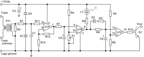
The approximately 8kHz bi-polar pulses produced by DCC are coupled through the current-sensing pulse-transformer PT1. Resistor R2, at 1kΩ, provides a relatively low impedance termination for the transformer’s secondary winding while converting the current generated in the secondary winding to a voltage.
With large track currents, the voltage swings induced across R2 can become large and if not limited could easily damage U1, an LM324 quad operational amplifier. Diodes D1 and D3 are included to clip the maximum voltage swing appearing at Pin 5 of U1, to keep it in the safe range from about .3V negative (the rating of the LM324) to 11.4V positive. To accomplish this, diode D1 is a special high-speed Schottky barrier rectifier with a forward voltage drop of only .37V at 20mA, compared to a conventional diode’s .7V drop. Including R1 limits the current in D1 and D3 while C1 provides filtering of the input signal.
The first stage of U1, namely U1A, is set up as a voltage amplifier with a gain of 100 determined by the ratio of R13 divided by R12. R11 is set equal to R12 for best amplifier operation. This amplification is essential to achieving the super sensitivity of the DCCOD. Minute track currents result in very low signals at the junction of R11 and C1. Having them boosted by a factor of 100 provides improved signal levels out of Pin 7 of U1. Capacitor C4 and resistor R7 provide a low-pass filter to take out the ripple effects created when U1A is in transition between being totally high and totally low. This way the input to Pin 9 is a clean signal.
The second stage of U1, namely U1B, is set up as a voltage comparator. Anytime the voltage input on Pin 9 becomes greater than that set on Pin 10, the output of U1B, Pin 8, switches from high to low. Potentiometer P1 controls the detection sensitivity by setting the reference switching point for U1B on Pin 10. Using the R4 value of 100kΩ, Pin 5 is adjustable between 0 and 1.1 volts. When Pin 8 is low it lights the L1 monitoring LED to show the block as occupied.
The product of R8 and C5 determines the turn-off delay, and the product of R3 and C5 determines the turn-on delay as long as R3 is considerably smaller than R8. Thus you can easily change the delay times if you wish. I enjoy the rather long 3.5s turn-off delay, which not only greatly minimizes the problems of intermittent contact, but also simulates the massive, slow-moving relays used in prototype track circuits.
The third stage of U1, U1C, is set up as another voltage comparator with its input being the output of the time delay circuit. With equal values of R5 and R6, the switching point of U1C is set at half the supply voltage or 6Vdc. The output of U1C, Pin 14, drives the open collector output transistor. When Pin 14 is low, to indicate block clear, transistor Q1 is “off” resulting in its collector terminal, the output of the detector, being an open circuit. When Pin 14 is high, indicating block occupied, the base of Q1 becomes positive causing the transistor to conduct resulting in the collector being effectively connected to ground.
ASSEMBLING THE DCCOD
The parts layout drawing is shown as Fig. 4-2 and the parts list is in Table 4-1.

Ready-to-assemble DCCOD circuit boards and the PTI current sensing pulse-transformer are available from JLC Enterprises, or you can purchase either complete kits, or assembled and tested boards from SLIQ Electronics.
Do-It Yourselfers assembling a large number of detectors using boards purchased from JLC Enterprises, and then providing their own electronic parts, can achieve costs at around $8 to $9 per detector. With smaller quantities, a more typical cost is $10 to $12 per detector. Complete kits as well as assembled and tested have higher prices. For example, effective January 2016, SLIQ Electronics lists the kit price at $10 and assembled and tested at $17.
Typically the kit route is the most economical approach for a small number of cards. Also, purchasing kits saves time from not having to place orders for electronic parts plus it saves on shipping and handling charges and minimum quantity fees which can mount up very quickly to $30, or significantly more, when ordering from multiple suppliers.
Table 4-1. DCC Optimized Detector Parts List (Rev. E)
(In recommended order of assembly)
|
Qnty. |
Symbol |
Description |
|
2 |
R1,R2 |
1.0KΩ resistors [brown-black-red] |
|
1 |
R3 |
220KΩ resistor [red-red-yellow] |
|
3 |
R4-R6 |
100KΩ resistors [brown-black-yellow] |
|
1 |
R7 |
10KΩ resistor [brown-black-orange] |
|
1 |
R8 |
3.3MΩ resistor [orange-orange-green] |
|
2 |
R9,R10 |
1.0KΩ resistors [brown-black-red] |
|
2 |
R11,R12 |
10KΩ resistors [brown-black-orange] |
|
1 |
R13 |
1.0MΩ resistor [brown-black-green] |
|
1 |
D1 |
Fast Schottky barrier rectifier (Mouser 625-SD103A or C) |
|
1 |
D2 |
1A, 100V diode (Mouser 625-1N4002E-E3/73 or Jameco 76961) |
|
1 |
D3 |
1A, 100V high speed diode (Mouser 625-1N4934-E3) |
|
1 |
S1 |
14-pin DIP socket (Jameco 112214) |
|
1 |
S2 |
5-pin Waldom side entry connector (Mouser 538-09-52-3051) |
|
1 |
C1 |
.01µF monolithic capacitor (Jameco 332647) |
|
3 |
C3-C5 |
1.0µF, 35V tantalum capacitors (Jameco 33662) |
|
1 |
P1 |
10KΩ potentiometer (Jameco 94714) |
|
1 |
Q1 |
2N4401 small signal transistor (Jameco 38421) |
|
1 |
L1 |
Red diffused size T1 LED (Jameco 333851) |
|
1 |
U1 |
LM324N quad op amp (Jameco 23683) |
|
1 |
W1 |
No. 22 solid insulated hook up wire or equivalent (see text), cut as required (Jameco 36856 with .045-inch insulation OD gives you 6-turn capability) |
|
1 |
PT1 |
Current-sensing pulse-transformer (JLC PT1) |
Author’s recommendations for suppliers given in parentheses above with part numbers where applicable. Equivalent parts may be substituted. Resistors are ¼W, 5 percent with color codes given in brackets. Note: C2 is not used with DCCOD Rev. E. Also, for higher track current applications, e.g. O-scale, it is recommended to use 1/2W resistors for R1 with leads bent so resistor mounts approximately 1/8” above the circuit board.
For those wishing to assemble their own, the basic skill required is PC-card soldering. If this is new for you, make doubly sure that you have thoroughly digested the information on PC card soldering in Chapter 1 of the C/MRI User’s Manual V3.0.
The order of parts assembly is not critical, but for the sake of having a plan, follow the steps in order and check off the boxes as you complete each one. I have included a [+] after the symbol for each part where polarity of assembly is important. As a further aid to assembly, the positive pads for polarity sensitive capacitors, the LED and Pin 1 of the IC socket are square. Also, on capacitors and the LED, the longer lead is the positive lead. Once you have one DCCOD assembled and operating correctly, you can use it as a pattern for assembling additional cards. Because this may be your first card assembly, I will go into more detail in the following assembly steps.
□ R1-R13. Make 90-degree bends in the leads of each resistor so it is centered between its two holes and the leads just fit. Insert and solder while holding the part flat against the card, then trim the leads. Note: If you are using DCC boosters with greater than 5A capability, it is recommended to replace R1 with a 1/2W resistor. Additionally, if you are unsure of the resistor values or have difficulty in reading the color coding bands, as might be the case if substituting 1% resistors which have extra bands or because color recognition may not be clear, it is a good idea to use a VOM set to its resistance range to check the resistor values before insertion.
□ D1-D3[+]. Install in the same manner as the resistors but make certain that the banded end of each diode is oriented as shown in Fig. 4-2. Diodes D2 and D3 are very similar except for the part number so double check the part numbers and make certain that you install the high-speed diode, the 1N4934, in the D3 location. The banded end of the fast Schottky barrier rectifier, a special glass diode, is sometimes hard to see. Take special care in locating the band and if required use a magnifying glass to double check the band orientation.
□ S1[+]. Making certain that you have all 14 pins properly in their respective holes with the correct orientation for Pin 1, hold the socket tight against the board as you solder the pins. If you are not sure of the correct orientation for Pin 1, see Fig. 1-7 of the C/MRI User’s Manual. As with any multi-pin part, solder only a couple pins first, those on opposite corners of the socket. Reheat as necessary to make certain that the socket is firmly against the board, then solder the remaining pins.
□ S2. Install this 5-contact side-entry connector by first hooking the nylon retaining fingers over the card edge, then feeding the metal contact pins through the card holes. Make sure all five pins pass through the holes. Hold the connector shell tightly against the card as you solder.
□ C1. Insert this component with the capacitor standing perpendicular to the card, solder and trim the leads.
□ C3-C5[+]. Insert these components with the capacitor standing perpendicular to the card. Make sure that the + leads, the longer of the two leads, also denoted by a small + sign, go into the + holes as shown in Fig. 4-2. Incorrect polarity will damage these capacitors. Solder and trim the leads.
□ P1. Install this potentiometer as in Fig. 4-2, push the three prongs all the way into the holes as you solder. You may need to adjust the back, single, prong a little so the potentiometer dial stands up perpendicular to the card.
□ Q1[+]. Spread the leads of this transistor slightly to fit the three holes, making sure the center (base) lead goes into the hole closest to P1, and that the flat side of Q1 faces the direction shown in Fig. 4-2. Push it in only far enough for it to fit snugly without stressing the leads. Solder and trim the leads.
□ L1[+]. Note the orientation of flat side and + hole (longer lead) in Fig. 4-2. With needle-nose pliers, hold the leads securely next to the housing and bend at right angles as in Fig. 4-2 detail. The LED sticks out over the edge of the card so you can see it when the detectors are plugged into their motherboard. Once bent and properly fitted to the card, solder and trim the leads.
□ U1[+]. Insert the LM324 IC making sure you have the correct Pin 1 orientation and that all pins go into the socket. If unsure of the correct procedure for inserting, and extracting, ICs see Fig. 1-7 of the C/MRI User’s Manual.
□ W1. Start the primary winding for PT1 by cutting a piece of AWG 22 insulated wire about 12 inches long. I use solid wire as once in place it holds its position better but you might prefer stranded wire as it bends more easily. Also, you might desire to use heavier wire, especially in O-scale and above, so I will explain this option after the assembly steps. Thread one end of the wire through the center opening in PT1, the core, just like you would thread a needle. Wrap the wire tightly around the side of the transformer and back through the center hole.
Repeat this process until you have six passes through the core. Form the two wire ends so they are in position to fit into the holes next to connector S2. Cut the two leads so they extend about .25-in below the base of the transformer and strip away the insulation level with the base of the transformer. Note: Keep the turns tight and going around the side of the transformer, and not over the top, or curved surface. Doing the latter makes the completed assembly too tall when multiple DCCODs are plugged into the ODMB.
□ PT1. Insert the two leads of the transformer into the holes furthermost from connector S2 and the two primary lead wires into the two holes closest to S2. If required, readjust and/or re-trim the primary leads to get a proper fit. Once set, and with the transformer held firmly against the card, solder the two transformer leads. Pull snugly on the two primary leads, from the trace side of the board, to remove slack in the wires. Then solder and trim the two primary leads. Polarity orientation of the transformer and its primary wiring is not important.
□ Cleanup and inspection. For a professional-looking job and to help ensure that your card functions properly, follow the specific steps covered in Chapter 1 of the C/MRI User’s Manual regarding cleanup and inspection. This is an important step, so do not cut it short!
That completes the assembly steps for the DCCOD. To test your detector follow the procedure defined in the Testing Detector Operation section in Chapter 2. In particular, using the clip lead assembly illustrated in Fig. 2-9 is important because simply observing correct operation of the LED built into the detector does not verify that the overall detector is operating correctly.
The DCCOD card layout uses wide traces and spacing between traces so soldering problems should be minimized. There are only two active components, the IC and the transistor, so debugging is easy, especially because the IC is fitted in a socket.
Connections To ODMB When Using DCCOD
Fig. 4-3 shows how to connect ODMBs when using the DCCOD. Simply run the detector power bus to each ODMB, whether located together or distributed around your layout.
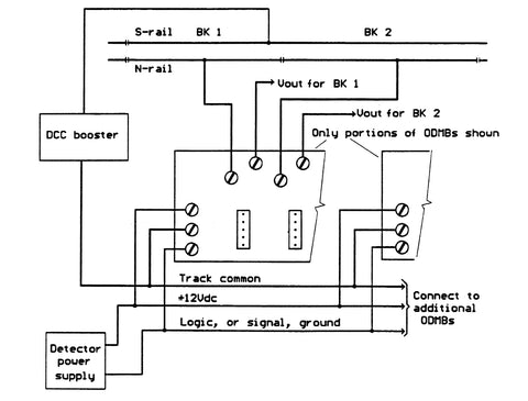
To power the DCCODs you need a power supply that provides a +12Vdc output as well as ground. Most C/MRI users make use of a surplus computer power supply as discussed in Chapter 19 of the V3.0 C/MRI User’s Manual. For connecting the detector’s output (Vout) to different devices (such as lamps, LEDs, relays and C/MRI inputs), consult Fig. 2-10 in Chapter 2. Additional connection information is also provided in Chapter 9.
SETTING DCCOD SENSITIVITY
One of the greatest attributes of the DCCOD, in addition to transformer coupling, is its very high sensitivity. To take full advantage of this capability, we need to adjust individually each DCCOD to as high a sensitivity setting as can be achieved, without it being so high that it will respond to the leakage resistance and the capacitive coupling that exists between the two rails, to falsely indicate a clear block being occupied. Such indications are frequently referred to as “false occupieds.”
Adjusting each detector to reach this “optimum sensitivity setting” requires two simple steps using the sensitivity adjustment potentiometer and corresponding test LED built into the DCCOD design. The procedure for the DCCOD is identical to that used with the OD and therefore will not be repeated here. Please refer directly to Chapter 3 for the details regarding how to adjust each of your DCCODs to their “optimized sensitivity” settings.
Using Different Wire Sizes And Number Of Turns With DCCOD
The number of wire turns you pass through the core of the current-sensing pulse-type transformer has a direct impact on the DCCOD’s sensitivity. Fig. 4-4 shows a plot of detector sensitivity versus number of turns.

How many wires you can feed through the transformer’s opening is a function of the AWG wire size used and the thickness of the insulation. I find that using six turns of AWG 22 wire works well. The six turns take up about 10.5-in. of wire. In Chapter 9 we will see that AWG 22 wire has a resistance of 1.61Ω/100 ft, so the resistance of the 6-turns calculates to be about .014Ω. With a track current of 5A, the detector voltage drop calculates as .07V which is insignificant. Even at a 10A, the voltage drop is only .14V and if you prefer a larger wire size can be used.
Staying with regular insulated wire but going up in size to AWG 20 you can fit in about five turns and with AWG 18 about four turns. The actual number of turns possible depends upon the thickness of the insulation and how diligent you are about threading the wire through the opening. For example, using regular house wiring AWG 12, you are limited to a single pass. To retain 6-turns with wire sizes greater than AWG22 you might want to consider using the insulated wire used in transformer and magnet windings because of its much reduced insulation thickness.
If preferred you can simply pass the track feeder wire right through the transformer opening rather than routing it through the ODMB and the S2 connector on DCCOD. This can be handy for distributed applications that do not use the ODMB. This way the track feeder is not broken to fit in the detector. Such applications may be appealing to O-scale and larger, where very large track currents are involved. However, I find the modularity provided by a separate plug-in detector per block offers great advantage.
At six turns, the Rev. E design is about two times more sensitive than the original design DCCOD. However, the more significant enhancement is the improved immunity to stray pickup from the wiring associated with other detectors. This immunity enables higher sensitivity settings on the layout without the annoyance of false occupancy caused by train movement in non-related blocks.
The wiring diagrams presented in the next chapter will show how both the DCCOD and the OD can be integrated into a DCC layout, to take advantage of optimized block occupancy detection.